[=x-=x=-=x=-=x=-=x=-=x=-=x=-=x=-=x=-=x=-=x=-=x=-=x=-=x=-=x=-=x=-=x=-]
[<<>><<>><<>><<>><<>><<>><<>><<>><<>><<>><<>><<>><<>><<>><<>><<>><<>]
[=x-=x=-=x=-=x=-=x=-=x=-=x=-=x=-=x=-=x=-=x=-=x=-=x=-=x=-=x=-=x=-=x=-]
Stardate: 20220120.1746
Location: xiled rumination concentrator
Input Device: xrc console
Audio: aNONradio - Myocyte w/ DJ ffog
Visual: xrc interior, interior LED colers fading, cycling.
Emotional State: Fed.
[=x-=x=-=x=-=x=-=x=-=x=-=x=-=x=-=x=-=x=-=x=-=x=-=x=-=x=-=x=-=x=-=x=-]
1U Raspberry Pi NAS 3of3 (cont.) Previous phost[1]
After I realized I could repurpose the power supply, it got my
mind working. I decided that I would need to add 2 female USB
ports and 2 ON/OFF switches to the case. Luckily, I had those
items in my stash of electronic components.
Soldering is one of those things that I enjoy doing, but it takes
me awhile, especially since I don't do it too often. I had to
make 2 circuits, which basically looked like this:
+5V wire from power supply -> terminal block -> ON/OFF switch ->
USB jack > terminal block -> -5V wire from power supply
Since I get freaked out when doing anything electrical, I did a
5 volt USB LED light "hello world" circuit test with an external
USB 5 volt battery charger, breadboard, and jumper clips. Good
thing I did since I had the pinout reversed on the female USB
jack. Here's a pic.[2]
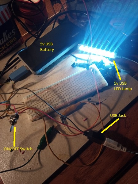 [2] LED "hello world" circuit test with external USB 5V battery.
After that I soldered the circuit together, crimped terminal
connectors to the wires from the power supply, and put in the
terminal block. Then I had to drill 2 holes in the front of the
1U case for the 2 ON/OFF switches. Here is a pic of the switches
mounted to the case. [3]
[2] LED "hello world" circuit test with external USB 5V battery.
After that I soldered the circuit together, crimped terminal
connectors to the wires from the power supply, and put in the
terminal block. Then I had to drill 2 holes in the front of the
1U case for the 2 ON/OFF switches. Here is a pic of the switches
mounted to the case. [3]
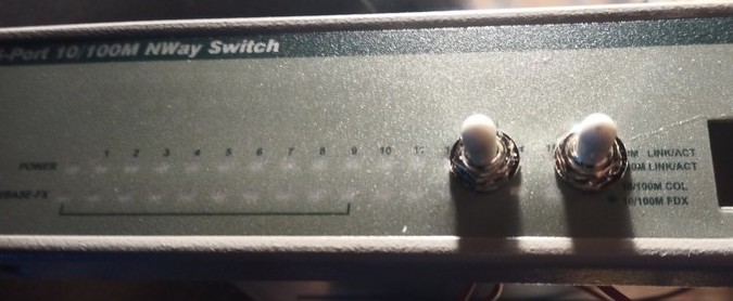 [3] ON/OFF switches installed on the front of the case.
For sanity's sake, I did another LED "hello world" circuit test
with the power supply, first with a battery with AC power and then
wall power. Another pic.[4]
[3] ON/OFF switches installed on the front of the case.
For sanity's sake, I did another LED "hello world" circuit test
with the power supply, first with a battery with AC power and then
wall power. Another pic.[4]
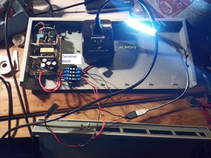 [4] LED "hello world" circuit test with power supply attached to AC power
Then I mounted the 2 Raspberry Pi2's and 2 WD Pi Drives. Western
Digital used to make Raspberry Pi drives and accessories under
their WDLABS project, which is now defunct. I picked up some drives,
cables, and a case during their fire sale. They had a tailor-made
cable that allowed you to connect the Pi and the drive using 1
microUSB cable, which is mounted in the 2 USB jacks. Here is a
pic of the case with the Pis.[5]
[4] LED "hello world" circuit test with power supply attached to AC power
Then I mounted the 2 Raspberry Pi2's and 2 WD Pi Drives. Western
Digital used to make Raspberry Pi drives and accessories under
their WDLABS project, which is now defunct. I picked up some drives,
cables, and a case during their fire sale. They had a tailor-made
cable that allowed you to connect the Pi and the drive using 1
microUSB cable, which is mounted in the 2 USB jacks. Here is a
pic of the case with the Pis.[5]
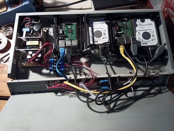 [5] 1U case internals with 2x Raspberry Pi2 and 2x WD Pi Drives
For the Pis, I used openmediavault[6] for both NAS servers, which
I have used in the past and had no problems. Here is a pic of
the NAS booting up when attached to mains power. [7]
[5] 1U case internals with 2x Raspberry Pi2 and 2x WD Pi Drives
For the Pis, I used openmediavault[6] for both NAS servers, which
I have used in the past and had no problems. Here is a pic of
the NAS booting up when attached to mains power. [7]
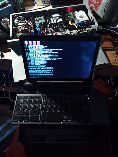 [7] Testing NAS attached to mains power.
After that, I tidy'd the cabling and closed her up. Obligatory
decals were added to cover most of the unused holes from the
switch. I also included 2 USB extension cables to each Pi for
attaching external storage and backups without opening the case.
Here's the front panel pic.[8]
[7] Testing NAS attached to mains power.
After that, I tidy'd the cabling and closed her up. Obligatory
decals were added to cover most of the unused holes from the
switch. I also included 2 USB extension cables to each Pi for
attaching external storage and backups without opening the case.
Here's the front panel pic.[8]
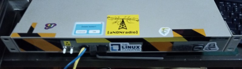 [8] 1U Pi NAS front panel
Here's a pic of the 1U Pi NAS mounted in my desk. [9]
[8] 1U Pi NAS front panel
Here's a pic of the 1U Pi NAS mounted in my desk. [9]
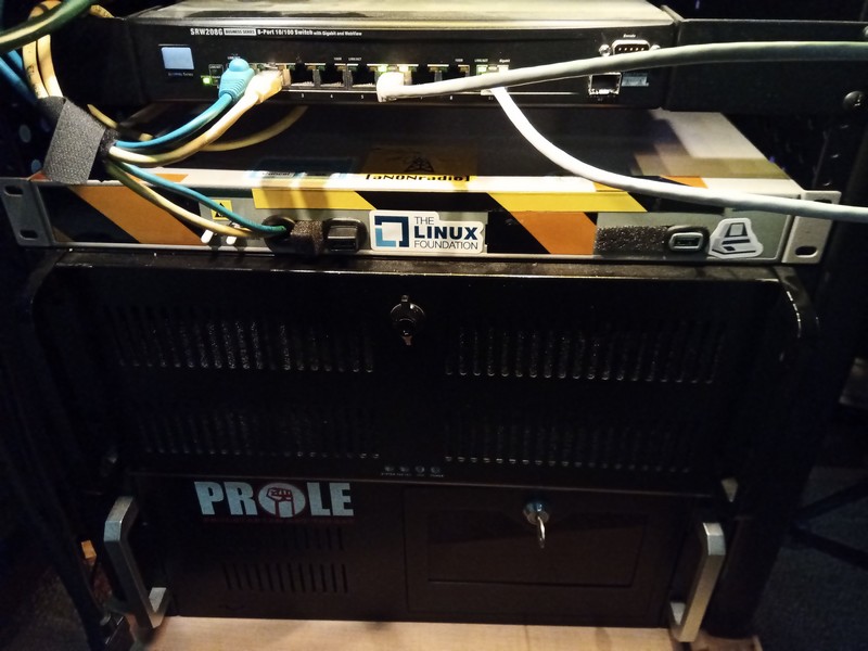 [9] 1U Pi NAS mounted in the rack on the left side of the lab desk.
The Pi works out pretty good for now. There are other modifications
I would like to do, but kept those for another time. Overall, I had
fun putting this together. I probably should take more breaks,
especially when soldering and also remove my contacts when I solder
since I am myopic. Good thing that Raspberry Pi 2 is good enough
for this project since it doesn't use as much power as the newer
Pis. I should run some tests. Also, the way I put it together
makes it easy to repurpose if/when I need to put different devices
in the case.
[1] gopher://sdf.org/1/users/xiled/phlog/2022/20220118_1u_pi_nas_2of3
[2] LED "hello world" circuit test with external USB 5V battery.
[3] ON/OFF switches installed on the front of the case.
[4] LED "hello world" circuit test with power supply attached to AC power
[5] 1U case internals with 2x Raspberry Pi2 and 2x WD Pi Drives
[6] https://www.openmediavault.org/
[7] Testing NAS attached to mains power.
[8] 1U Pi NAS front panel
[9] 1U Pi NAS mounted in the rack on the left side of the lab desk.
20220117_1u_pi_nas_1of2
- 1U Raspberry Pi NAS (part 1of2)
20220118_1u_pi_nas_2of3
- 1U Raspberry Pi NAS (part 2of3, OK, I lied.)
20220120_1u_pi_nas_3of3
- 1U Raspberry Pi NAS (part 3of3)
[=x-=x=-=x=-=x=-=x=-=x=-=x=-=x=-=x=-=x=-=x=-=x=-=x=-=x=-=x=-=x=-=x=-]
[9] 1U Pi NAS mounted in the rack on the left side of the lab desk.
The Pi works out pretty good for now. There are other modifications
I would like to do, but kept those for another time. Overall, I had
fun putting this together. I probably should take more breaks,
especially when soldering and also remove my contacts when I solder
since I am myopic. Good thing that Raspberry Pi 2 is good enough
for this project since it doesn't use as much power as the newer
Pis. I should run some tests. Also, the way I put it together
makes it easy to repurpose if/when I need to put different devices
in the case.
[1] gopher://sdf.org/1/users/xiled/phlog/2022/20220118_1u_pi_nas_2of3
[2] LED "hello world" circuit test with external USB 5V battery.
[3] ON/OFF switches installed on the front of the case.
[4] LED "hello world" circuit test with power supply attached to AC power
[5] 1U case internals with 2x Raspberry Pi2 and 2x WD Pi Drives
[6] https://www.openmediavault.org/
[7] Testing NAS attached to mains power.
[8] 1U Pi NAS front panel
[9] 1U Pi NAS mounted in the rack on the left side of the lab desk.
20220117_1u_pi_nas_1of2
- 1U Raspberry Pi NAS (part 1of2)
20220118_1u_pi_nas_2of3
- 1U Raspberry Pi NAS (part 2of3, OK, I lied.)
20220120_1u_pi_nas_3of3
- 1U Raspberry Pi NAS (part 3of3)
[=x-=x=-=x=-=x=-=x=-=x=-=x=-=x=-=x=-=x=-=x=-=x=-=x=-=x=-=x=-=x=-=x=-]
.:[ HOME ]:.